Alarm Relay Wiring
Overview
The M262 Logic/Motion Controller has integrated relay connections that can be wired to an external alarm.
Wiring Stripping and Wire Sizes
The alarm relay is wired by means of a 5.08 mm pitch removable screw terminal block on the front face of the M262 Logic/Motion Controller. For details, refer to Rules for Terminal Blocks.
Using the Alarm Relay for the Actuator Power Supply
Proceed as follows to use the Alarm relay for the actuator power supply:
|
Step |
Action |
|---|---|
|
1 |
Switch on the power supply of the M262 Logic/Motion Controller using the main contactor. |
|
2 |
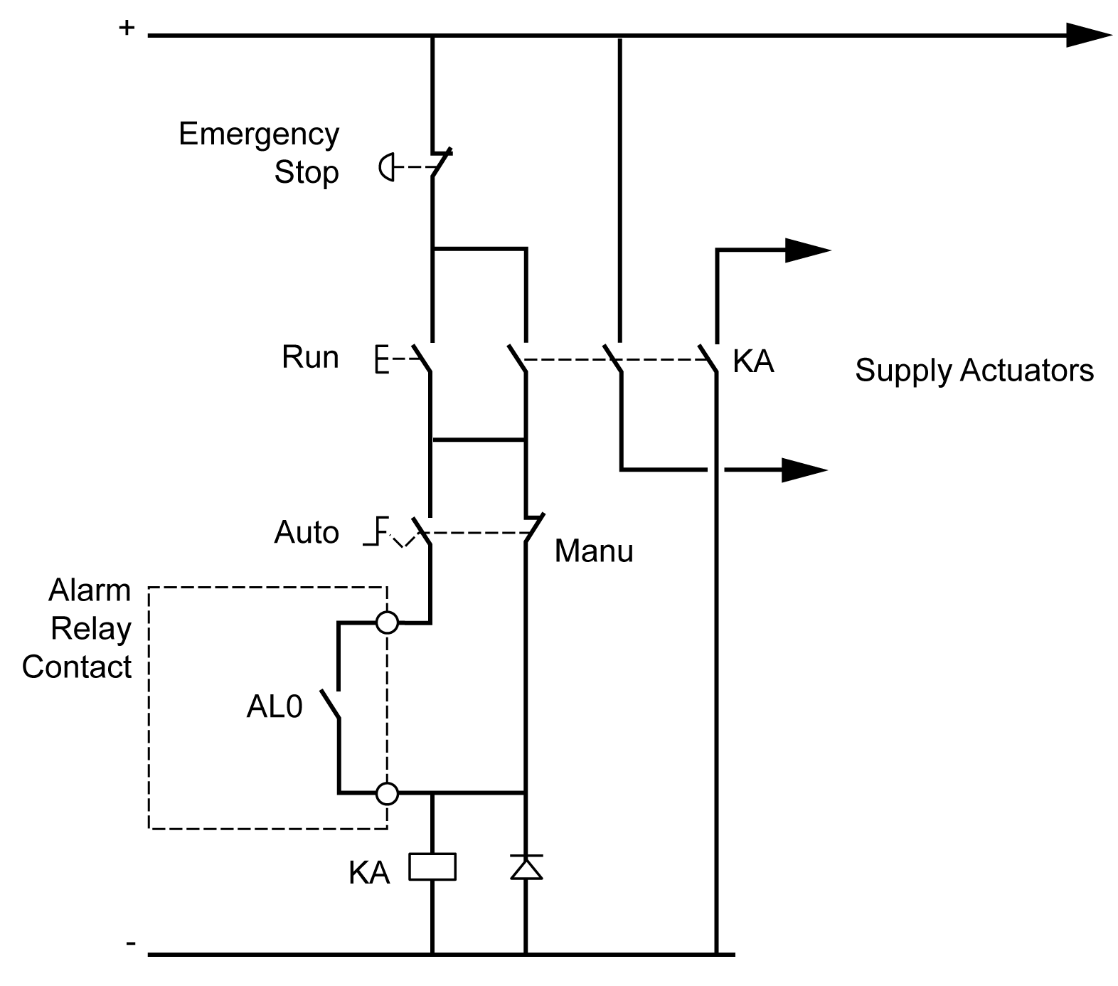
When the M262 Logic/Motion Controller is powered on, switch on the output power supply for the actuators using the KA contactor. The following wiring diagram shows an M262 Logic/Motion Controller supplied by direct current: 
In AUTO run mode, the KA contactor is controlled by the alarm relay from the power supply module. |
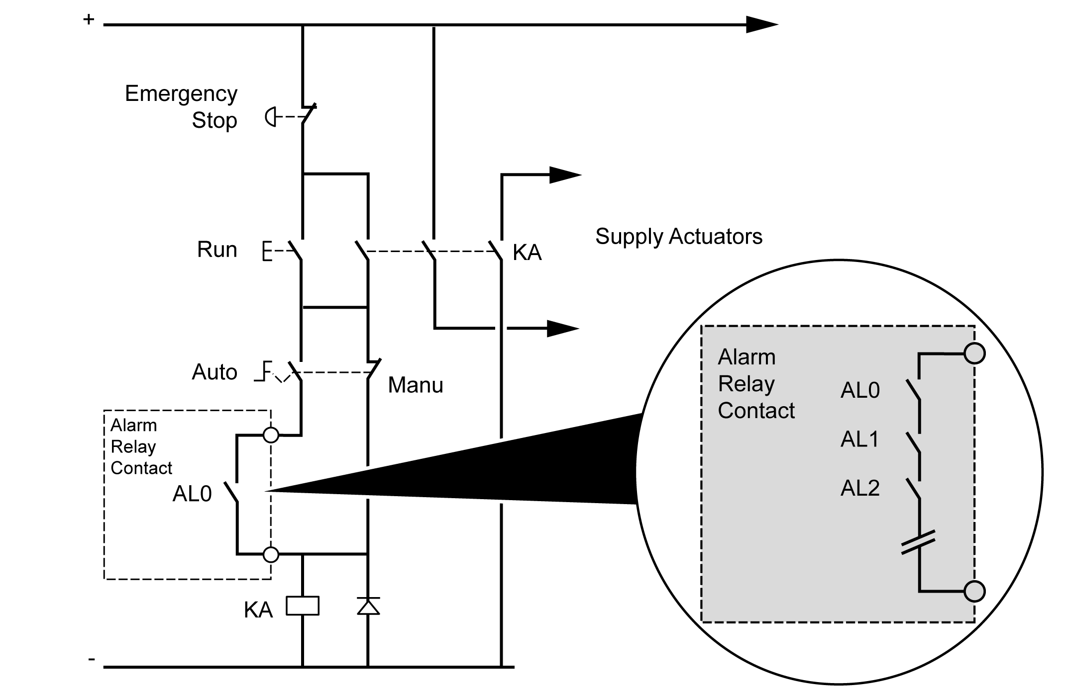
If your system comprises multiple M262 Logic/Motion Controllers installed in multiple racks, set the alarm relay contacts in all controllers in series (AL0, AL1, AL2, and so on), as shown in the following diagram:
